Introduction
The use of ground control points in our data allows us to generate more accurate models and products. Ground control points assist in geo-referencing the data and improving the relative and absolute accuracy of the product. Pix4D calls for the use of a minimum of 3 ground control points but recommends to use between 5 and 10 in a data set. It is important for the pilot to use very distinguishable ground control points during data acquisition as well as keep detailed field notes on geographic locations of the points and from where the data point was taken. Ground control points can be used as checkpoints within the data set but checkpoints are not always ground control points. Checkpoints are used to assess the accuracy of the data and generated models. Differences in the initial and computed checkpoints are generated in the quality report and tell the user the amount of error within the data. Ground control points and checkpoints help the user generate and monitor an accurate data set.
Method
Begin by importing the images from the data set to Pix4D, either by selecting individual images or the entire data set. We are using the data acquired from the Wolfpaving flights consisting of 69 total images. Once the images are uploaded ensure the correct Coordinate system has been selected, we are using WGS 84 UTM Zone 16N, pictured in Figure 1. It is important to change the camera shutter from Global Shutter to Linear Rolling Shutter. This will allow Pix4D to correct for the Rolling Shutter effect, pictured in Figure 2.
 |
| Figure 1: Initial Processing Settings |
 |
| Figure 2: Camera Model Parameters. |
Now that the data has been uploaded we can input the Ground Control Points through the GCP/ MTP Manager, pictured in Figure 3. Then, import the correct GCP file, we are using the Wolfpaving text file pictured in Figure 4. Figure 5 shows what the GCP manager will look like when the GCP's are input correctly.
 |
| Figure 3: GCP Manager |
 |
| Figure 4: Input ground control points. |
 |
| Figure 5: GCP Manager. |
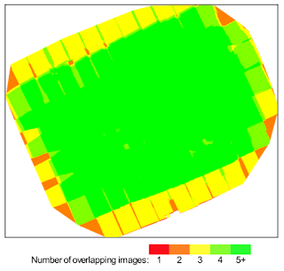
Similar to previous labs we can now run the initial processing on its own. Once the initial processing is complete we can view the generated Quality Report, which will show us details such as total processing time, quality checks and areas of error in the data set. Pictured below is the initial summary, quality check and model previews of the Quality Report. Figure 7 shows the overlap that was achieved in the the data set. Due to the grid pattern flown, pictured in Figure 8, in the data acquisition there is lower overlap around the perimeter of the model.
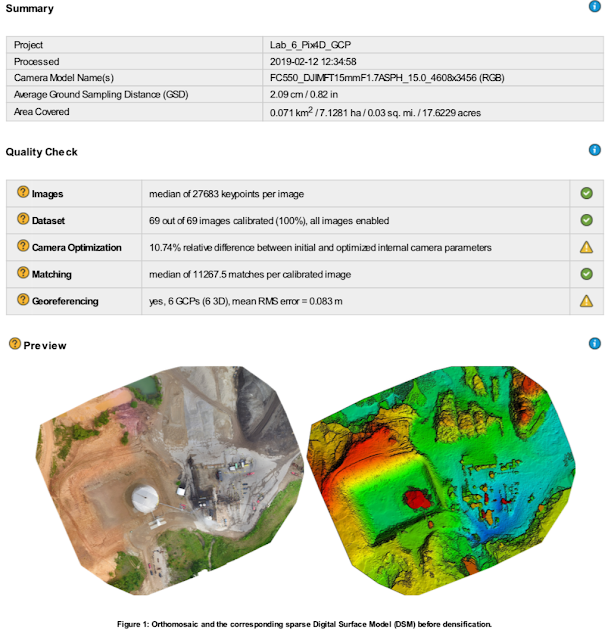 |
| Figure 6: Quality Report |
 |
| Figure 7: Image Overlap |
 |
| Figure 8: Flight Path. |
We can now continue to process the data by running steps 2 and 3. Be sure to uncheck "initial processing" and check "point cloud and mesh" and "DSM, orthomosiac and index". Processing is complete and we can analyze the models that have been generated. We will need to go in and manually adjust the ground control points. There was an issue with the UAV/ Sensor data with relations to the true elevation of the ground. Access the GCP manager again and manually move the GCP's to their desired position. Figures 9 and 10 show the GCP manager, the bottom right hand side of the figures show the different GCP frames in which the user can do adjustments. Doing the manual GCP adjustments will allow for a more accurate data set, it will assist the user with map alignment when using base maps from different sources.
 |
| Figure 9: GCP manager and adjustment |
 |
| Figure 10: GCP adjustment |
Figure 11 depicts what the corrected GCP should look like.
 |
| Figure 11: Adjusted GCP |
Now that our data is processed and the ground control points have been adjusted we can review our models and move the data into ArcMap to generate an orthomosiac and DSM map. Figures 12 and 13 show the 3 dimensional point cloud model generated by Pix4D. The overall quality and accuracy of the model is fairly good, especially in generating the terrain. The areas of infrastructure tend to have some errors as shown in Figure 13. Due to the angle of the sensor during data collection the sides of buildings and machines have been distorted. Figure 13 shows tops of buildings or machines "floating" in the air. This can be corrected with more images taken at other angles during data collection, but may not always be necessary to still maintain accuracy in the data.
 |
| Figure 12: 3 Dimensional Point Cloud |
 |
| Figure 13: Errors in the 3 Dimensional Model |
Discussion
Through the use of ground control points we were able to achieve a higher level of accuracy with this data set. It was clear in the last project there were errors within the data such as the major misalignment of the orthomosiac and DSM when inlayed into a base-map. Figure 14 and 15, below, show a higher accuracy DSM and orthomosiac. We are able to see that the DSM and orthomosiac we have generated in Pix4D almost perfectly line up with the base-map via the ponds at the top of the model. The models are not perfect as we did see slight errors in the data, the initial quality report cautions us that there are issues with the GCP's under the "Quality Check" referenced in Figure 6. Figure 16 states the possible issues with regards to the ground control points in our data. This problem could be fixed with the use of more ground control points throughout the mission area. As shown in Figure 14 and 15 the GCP's used seem to be clustered around the center of the models. Another possible way to fix this issue would be to use more distinguishable GCP's that Pix4D would have an easier time identifying and geo- referencing. Overall the quality and accuracy has increased with these models. Presenting the misaligned models to a client would not be very professional, this shows us the need for GCP's in our data sets.
 |
| Figure 14: Wolf Paving DSM Map |
 |
| Figure 15: Wolf Paving Orthomosiac Map |
 |
| Figure 16: GCP errors |
Conclusion
Ground control points in our data set allow for increased absolute and relative accuracy in the models that we generate when used correctly. It is important for the user to ensure that the data they are using from the ground control points is accurate. It is up to the pilot to create or use enough and very distinguishable ground control points as well as keep detailed field notes. If we/ Pix4D are not able to identify the ground control points in post processing the data could be less accurate. We were able to see through the use of ground control points the increase in accuracy from previous models generated without GCP's. Our models were misaligned when inlayed into a base-map without the use of the ground control points. When were were able to use ground control points we did not encounter the same misalignment errors. Ground control points are a necessary tool to ensure the highest level of accuracy when generating models, drastically reducing the margin of error in geo-referenced data sets.


Comments
Post a Comment