Lab 10 Processing Oblique Imagery
Introduction
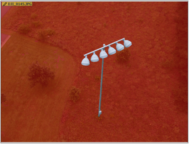
In this lab we used oblique imagery to create 3 dimensional models of a truck and a baseball field light pole. Oblique imagery allows the user to capture objects at many different angles and when stitched together in the point cloud creates an accurate 3D object. Oblique imagery is different from the Nadir data used in past labs. Nadir data provides the user with a more accurate image for mapping and surveying, Nadir imagery will take away some of the warping of objects when the sensor is at an angle.
When processing oblique imagery it is important to annotate the images to create a more accurate and less busy data set. We do this to take out unwanted aspects of the data set such as backgrounds, sky or other unwanted objects that take away from the target. We are able to do this in Pix4D by selecting the area we want to get rid of or annotating the image. Image annotation can be done by three different methods within Pix4D, these methods are; carve, mask and global mask.
 |
| Figure 1: Annotation Techniques (Pix4D) |
Mask: The pixels that are masked are not used in processing.
- Removing an obstacle that appears in a few images.
- Removing the background of an Orthoplane.
- Removing the sky automatically.
Carve: 3D points located on the rays connecting the camera center and the annotated pixels are not used for processing. This is suitable for sky removal.
Global Mask: The pixels annotated are propagated to all the images. All these pixels are not used for processing. This is suitable for a consistent obstacle in all of the images such as a drone leg.
Method
In this lab we processed two data sets of oblique imagery and made necessary annotations to create accurate 3 dimensional models using the point cloud. The first data set was taken of a truck and the second was a baseball field light pole.
Truck
For this data set we began by uploading the necessary images to Pix4D and running the initial processing. Initial processing must be done before any image annotation can be done. Pictured below is the Quality Check from the initial processing report, we can see that all images were successfully used and there is a warning because there was no use of GCP's in this data set.
 |
| Figure 2: Quality Report |
Now we can begin annotating images, for this data set we initially annotated 15 images out of the 69 images in the data set using the carve tool. To annotate images you select an individual image in the layer window, the image will then show up in the properties window. You can select which annotation technique you will want to use in for the data, we used carve, pictured in Figure 3.
 |
| Figure 3: Annotating the Image |
In order to annotate the image hover the mouse over the desired area that will not be included in the processing ie. background or sky. The annotation tool will select those pixels and remove them from the processing of the point cloud.
 |
| Figure 4: Partially annotated truck image |
 |
| Figure 5: Fully annotated truck image |
As shown in figures 4 and 5 the background and undesired area was selected using the carve tool. This area will now not be included in the processing of the point cloud. After annotating the desired amount of images we can run the point cloud and mesh. After running the point cloud and mesh we can see how the model turned out. We then reoptimized and annotated 3 more images, then, ran the point cloud and mesh again. Pictured below is the final 3D model of the truck.
 |
| Figure 6: Point cloud and triangle mesh truck (right) |
 |
| Figure 7: Point cloud and triangle mesh truck (left) |
 |
| Figure 8: Point cloud and triangle mesh truck (back) |
Light Pole
For the light pole we went through the same steps as we did for annotating the truck. Again using the carve tool to annotate 15 images in the data set.
 |
| Figure 9: Quality Check |
From the quality check we can see again, all images were used and there were no GCP's used in this flight.
 |
| Figure 10: Annotated light pole (partial) |
 |
| Figure 11: Annotated light pole (full) |
 |
| Figure 12: Point cloud and triangle mesh light pole |
 |
| Figure 13: Point cloud and triangle mesh light pole |
Discussion
From the point cloud and triangle mesh images we can see obvious errors in the targeted object. On the truck there are areas cut off along the bottom of the truck and there are partial areas of the background left. The same issue is present on the light pole with partial areas of the background still showing as well as pieces of the object missing (top of pole below the lights, areas between the lights). This may be due to annotating too close to the objects and removing some of the pixels of the object. It is important to come close to the object but to not select any pixels of the target. The back ground may still be showing up due to most of the annotated images not being fully annotated. Most of the images were annotated around the vicinity of the target object, shown in Figures 4 and 10. This can be fixed by going back and annotating more of the back ground in the same or new images.The flight path of the UAV also comes into play when selecting images to annotate as well as the final output. If the flight path does not accurate capture angles of the object they will be left out of the data set. It is important to select/ annotate enough images at different angles to accurately capture all of the target object. If the flight path is poor and too many angles are missed the data set is not successful and should not be used.


Comments
Post a Comment